


Packaging box room photovoltaic installation
The installation of photovoltaic systems in packaging box integrated houses (referred to as "packaging box houses") requires the combination of their modular, lightweight, and movable characteristics to achieve efficient power generation while ensuring structural safety. The entire process can be divided into four stages: preliminary preparation, core installation, debugging and grid connection, and acceptance and maintenance. Each stage must strictly follow the building specifications and photovoltaic technology standards. The specific process is as follows:
1、 Preliminary preparation: Evaluation and planning (key prerequisite)
The core of this stage is to confirm whether it can be installed, how much to install, and how to install it, in order to avoid rework or safety hazards in the later stage.
1.Structural safety assessment
The main body of the packing box room is a steel structure or aluminum alloy frame, which needs to be inspected by a professional organization first:
-Roof load-bearing capacity: The weight of photovoltaic modules (including brackets) per square meter is about 15-25kg. The load-bearing capacity of the top purlins and main beams of the box house needs to be confirmed (at least 20% safety factor needs to be reserved to avoid frame deformation caused by long-term loads);
-Roof flatness: If there is a significant inclination or depression on the roof, leveling treatment (such as installing steel gaskets) should be carried out first to ensure that the photovoltaic bracket is installed firmly;
-Wind/snow resistance capability: Based on the climate of the project location (such as typhoon or snow covered areas), select the appropriate bracket wind resistance level (usually ≥ 12 level wind load) and snow resistance load (calculated with reference to the maximum snow depth in the local area).
2.Photovoltaic system planning
-Capacity design: Determine the photovoltaic installed capacity based on the electricity demand of the box room (such as daily lighting, air conditioning, equipment electricity). Typically, a single box room (about 20-30 square meters) can install a 2-5kW system (corresponding to 5-12 400W+components);
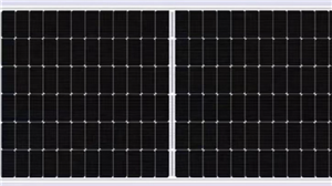
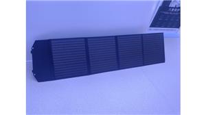
-Component selection: Prioritize the selection of * * lightweight photovoltaic modules * * (such as single glass modules weighing about 18kg/block, which is 30% lighter than double glass modules) to reduce roof loads; If the container room needs to be moved, flexible photovoltaic modules (weighing only 3-5kg/㎡, suitable for curved surfaces or temporary roofs) can be used;
-Grid connection methods: There are two types: "off grid" and "grid connected". Off grid systems require energy storage batteries (suitable for areas without power grids, such as temporary buildings on construction sites), while grid connected systems directly connect to the local power grid (requiring prior application for grid connection qualifications from the power company).
3. Preparation of materials and tools
-Core materials: photovoltaic modules, aluminum alloy/galvanized steel brackets (modular brackets suitable for box house roofs, no or minimal drilling required), inverters (single-phase/three-phase according to capacity, recommended models with anti backflow function), photovoltaic cables (flame retardant, suitable for outdoor environments), waterproof sealant (neutral silicone adhesive, preventing roof water leakage);
-Tools: electric drill (with dedicated drill bit to avoid damaging the roof panel of the box), level, torque wrench (to control the tightening force of the bracket bolts and prevent damage to the frame due to over tightening), crimping pliers, multimeter, etc.
2、 Core installation: step-by-step implementation (core process)
Step 1: Roof cleaning and foundation treatment
-Clean up the debris on the roof of the container room (such as dust, oil stains, sharp objects), check whether the roof panels are damaged or corroded, and if so, repair them first (such as replacing damaged color steel plates and applying anti rust paint);
-Mark the installation position of the bracket: According to the component size (such as 1660mm × 1002mm) and installation spacing (usually leaving a gap of 20-30mm between components for heat dissipation), use ink lines to mark the bracket fixing points, ensuring that the fixing points avoid the gap between the roof purlins (need to fall on the load-bearing purlins to avoid roof deformation).
Step 2: Photovoltaic bracket installation (key load-bearing structure)
-Select modular quick installation bracket * * (suitable for lightweight design of packaging box room, no welding required), first fix the bracket base: use self tapping screws (or expansion bolts, depending on the roof material) to fix the base on the roof purlin, with at least 2 screws per base, and the screws need to be coated with waterproof glue (to prevent rainwater from seeping into the box room through the screw holes);
-Installation of bracket crossbeam: Connect the crossbeam to the base with bolts, calibrate the levelness of the crossbeam with a spirit level (error ≤ 2mm/m), and ensure that the components are evenly stressed after installation; If it is installed obliquely (to improve the power generation efficiency, the obliquity is usually ± 5 ° of the local latitude), it is necessary to adjust the obliquity through the support slant support, and tighten all bolts with a wrench (refer to the support manufacturer's requirements for torque value, which is generally 25-35N · m).
Step 3: Installation of Photovoltaic Modules (Power Generation Core Components)
-Component handling: Handle with care to avoid collision with frames or glass (component glass is fragile, and frame deformation can affect power generation);
-Component fixation: Place the component on the support crossbeam and use pressure blocks (made of aluminum alloy material) to fix the component frame on the crossbeam. Each component should have at least 4 pressure blocks (1 at each corner, and 2 in the middle if the component size is large). The pressure block bolts should be tightened in place (with a torque of about 15-20N · m) to prevent the component from being blown by the wind;
-Component wiring: Connect components in a "series+parallel" manner (such as two components connected in series to form one series, multiple series and then parallel). When wiring, strip off the insulation layer of the cable (about 5-8mm in length), insert the male and female plugs into the component junction box, and lock them with buckles (to prevent loosening and poor contact). At the same time, use zip ties to fix the cable on the bracket (to avoid cable sagging and pulling the joint).
Step 4: Installation of Inverter and Distribution Box
-Inverter installation: Choose a location with good ventilation and avoid direct sunlight (such as on the side wall of the box room or on a separately built bracket on the roof), with a distance of ≥ 1.2m from the ground. Use expansion screws to fix the inverter bracket, and then mount the inverter on the bracket (ensuring that the inverter heat dissipation holes are unobstructed);
-Cable connection: Connect the "DC cable" of the photovoltaic modules in series to the DC input terminal of the inverter (note the distinction between positive and negative poles, reverse connection will burn the inverter), and then connect the inverter output terminal to the distribution box with an "AC cable" (circuit breakers and leakage protectors need to be installed to ensure electrical safety);
-Waterproof treatment: All outdoor cable joints (such as component junction boxes, inverter inlet and outlet lines) need to be covered with waterproof terminals and wrapped with waterproof tape 3-5 times to prevent rainwater from infiltrating and causing short circuits.
3、 Debugging and grid connection: ensuring the normal operation of the system
1.System detection (safety first)
-Insulation testing: Use a multimeter or insulation resistance meter to test the insulation resistance of the DC side (component to inverter), which should be ≥ 2M Ω (to prevent leakage);
-Wiring inspection: Check whether the positive and negative poles of all cables are reversed, whether the plugs are tightly inserted, and whether the circuit breaker is in the disconnected state to avoid short circuits after power on;
-No load debugging: Close the main switch of the distribution box, turn on the inverter, observe whether the inverter display screen starts normally (without error codes), and check whether the DC voltage and current are consistent with the theoretical values after the components are connected in series (such as two 400W components connected in series, with a DC voltage of about 80-90V).
2. Grid connection application and acceptance (compliance requirements)**
-Submit a grid connection application to the local power company and provide project information (such as photovoltaic system design scheme, box house structure inspection report, inverter qualification certificate);
-On site acceptance by the power company: check the system grounding (lightning protection grounding device needs to be installed, grounding resistance ≤ 4 Ω), anti backflow function (to avoid affecting the safety of the power grid when photovoltaic electricity is transmitted back to the grid), and metering device (bidirectional electricity meter needs to be installed to record the power generation and consumption);
-After passing the acceptance inspection, the staff of the power company will close the power grid and the system will officially enter the power generation state.
4、 Acceptance and maintenance: ensuring long-term stability
1.Completion acceptance
-Appearance inspection: The bracket is not deformed, the components are arranged neatly, the cable fixation is standardized, and the waterproof adhesive is not cracked;
-Performance testing: Continuously monitor the power generation for 24 hours, compare the theoretical power generation (calculated based on local light intensity), and the error should be ≤ 10%;
-Safety testing: Simulate short circuit and leakage situations, check whether the circuit breaker and leakage protector can trip in a timely manner (response time ≤ 0.1 seconds).
2.Daily maintenance (extending lifespan)
-Regular cleaning: Clean the surface dust and bird droppings of the components every 1-3 months (using a soft bristled brush or high-pressure water gun, water pressure ≤ 0.3MPa, to avoid scratching the glass);
-Inspection: Monthly check whether the bracket bolts are loose, whether the cable joints are oxidized, and whether the waterproof glue is aged (if it is aged, it needs to be re glued);
-Inverter maintenance: Clean the dust on the cooling holes of the inverter every six months to avoid overheating and shutdown; Check if the grounding system is intact after thunderstorm season.
Key precautions
1. Structural safety priority: It is strictly prohibited to install photovoltaics without evaluating their load-bearing capacity to avoid deformation or collapse of the box room frame;
2. Waterproof and anti-seepage: All roof boreholes and cable joints must be waterproofed to prevent rainwater from seeping into the interior of the box room (the roof panels of the packaging box are mostly made of color steel plates, and water seepage can cause internal moisture and equipment damage);
3.Compliance: The grid connected system must pass the acceptance of the power company, and unauthorized connections are prohibited (illegal grid connections may face fines and pose security risks to the power grid);
4.Mobile adaptation: If the packaging box room needs to be frequently moved, it is recommended to choose the "detachable photovoltaic bracket" for easy disassembly and relocation, avoiding repeated installation costs.
Through the above process, efficient integration of packaging box rooms and photovoltaic systems can be achieved, which not only meets the electricity needs of temporary buildings, but also conforms to the concept of green energy conservation. It is suitable for scenarios such as temporary dormitories, outdoor camps, and emergency resettlement sites on construction sites.
